SimplyCam V2. Tutorials
- SimplyCam V2
- Interface
- Toolbars
- Vectorization
- Settings
- Toolpath Manager
- Toolpaths
- Tutorials
Tutorial 1 - Open Jpg image, vectorize it and create the Engraving toolpath.
In this tutorial you will open an Jpg image, vectorize it and create the toolpaths to cut out the part.

Caution:
CNC machines are potentially dangerous. The post-processor can output code unsuitable for your machine's control. Check the Nc file before sending it to a CNC machine.
Step 1.
Open the raster file with the "Open" button.
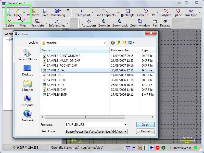
Step 2.
Select in "..\SimplyCam 2\Samples\" folder the SAMPLE1.JPG file.
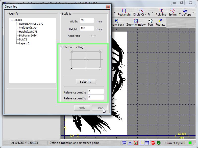
The Info panel will appear with the info and dimension of image.
Step 3.
Scale image to desidered dimension.
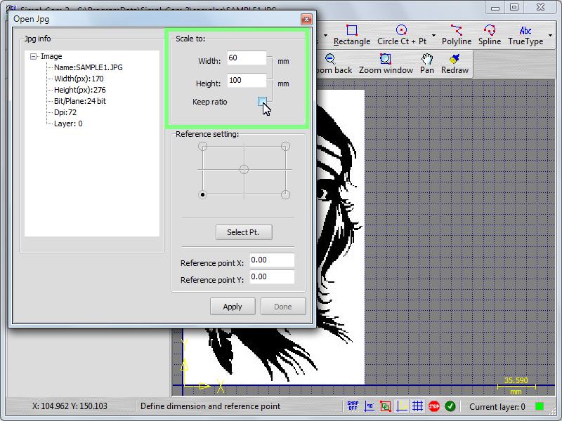
Step 4.
Define the reference point of image and press "Apply / Done" button.
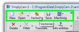
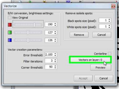
Press the "Vectorize" button.
Step 5.
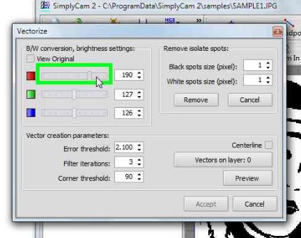
Move the RGB sliders to convert image in black and white.
Step 6.
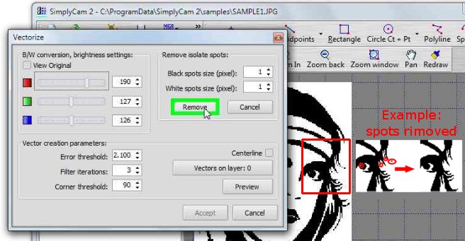
Remove the isolated spots for filtering the raster image.
Step 7.
Press the "Vectors on Layer" button.
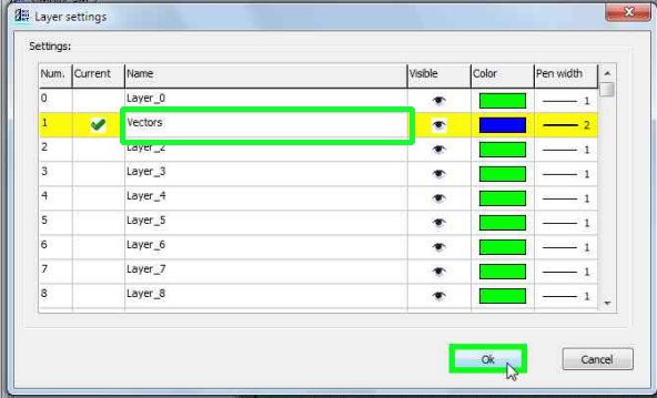
Step 8.
The "Layer setting" page appear. Set the "Current Layer" of 1
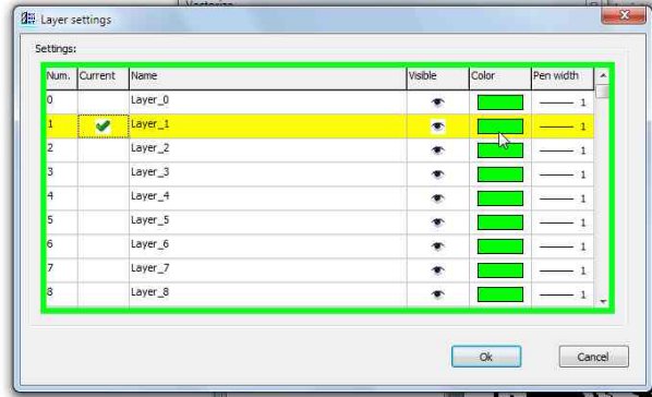
Step 9.
Set the "Color" to Blue. This change the color of all entities on Layer 1.
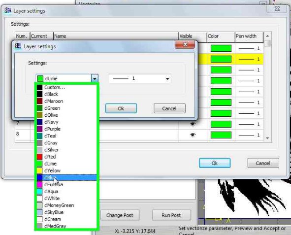
Step 10.
Set the "Pen width" to 2.
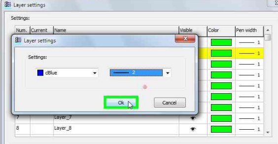
Step 11.
Change the "Layer name" in "Vectors" and press the "Ok" button.
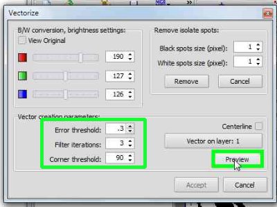
Step 12.
Set the vectorize parameter as showed below and press "Preview" button. The vector data (linee, polyline, ...) will appear.
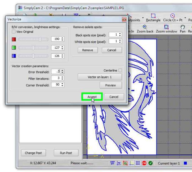
Step 13.
If the entities are correct press the "Accept" button.
Step 14.
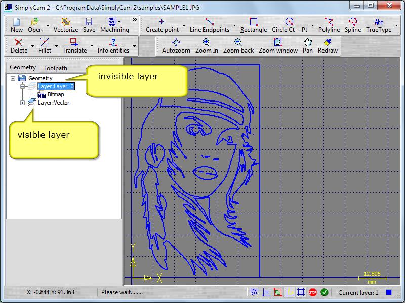
In Geometry tree view, right click with mouse on "Layer_0" and click on "On/Off" menu item.
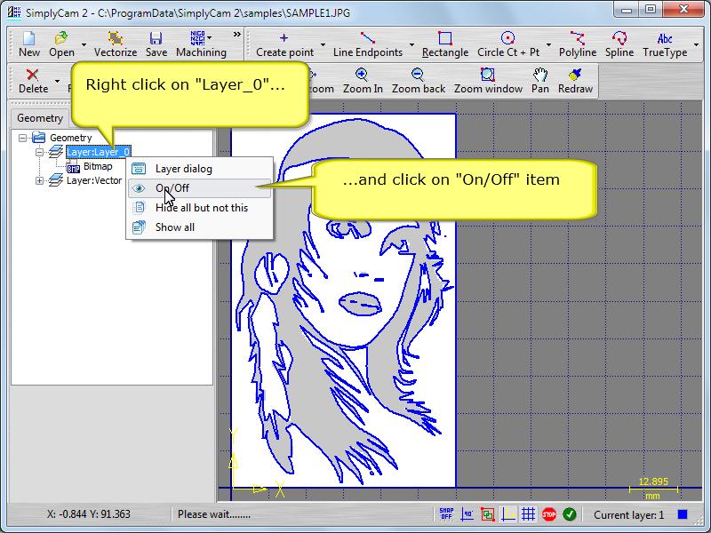
Step 15.
The Layer 0 is invisible. This hide the Jpg image on Layer 0
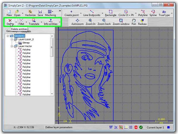
Step 16.
The graphic area showing the all geometry, without the Jpg image. Press in toolbar the "Delete" button.
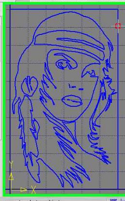
Step 17.
Pick the geometry such as indicate by red square.
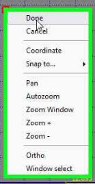
Step 18.
Confirm "Done" action by pressing the releted button in status-bar or with the drop down menu.
Step 19.
The geometry is displayed in graphic area without the external boundary.
Step 20.
Press "Save" button to save the vector data into .Dxf format or in .Snc (Simplycam format).
Step 21.
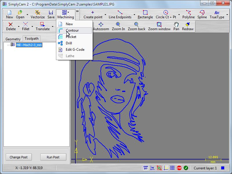
Press "Contour" in "Machining" menu to go in toolpath section.
Step 22.
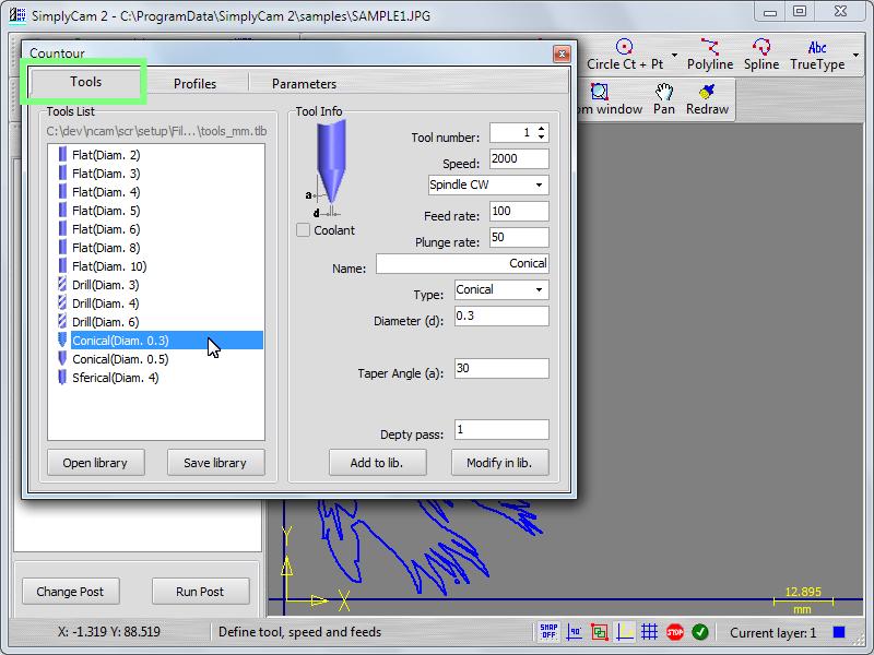
In Tool section click in the Tool List to select the tool. Set feeds and speed of the tool.
Step 23.
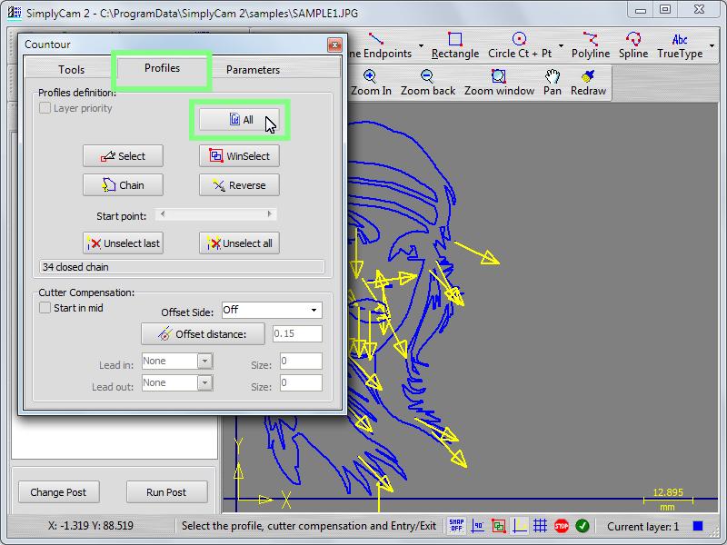
Click on the "Profiles" tab and press the "All" button.
All the entities are chained. The yellow arrows appears to indicate the start point of contour and the direction of contour.
The blue boundary is the chained profile.
In the "Cutter compensation" section, set the "Offset Side" on Off.
Step 24.
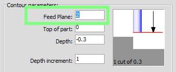
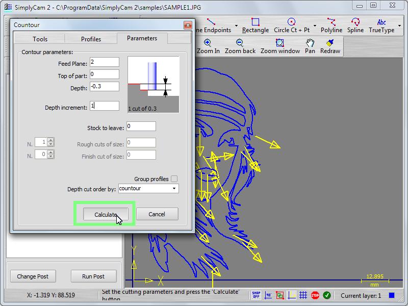
Click on the "Parameters" tab and set up the following parameters:
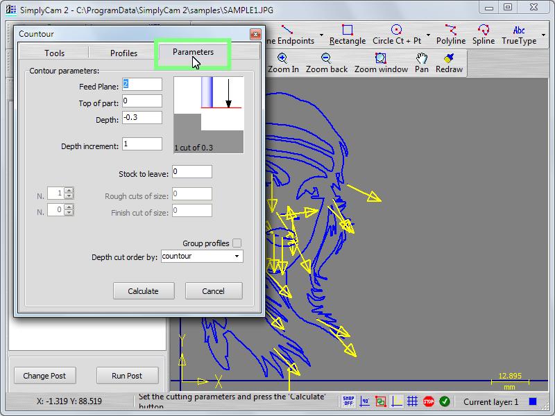
Feed plane: set the height that the tool rapids to (G0) before changing to the feed rate (G1) to enter in the part (absolute).
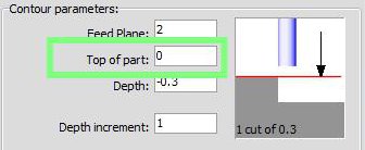
Top of part: set the height of the piece in the Z axis (absolute).
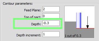
Depth: set the final machining depth (absolute).
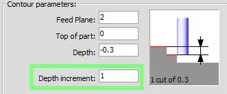
Depth increment: set the maximum amount of material to remove for each Z cut.
Step 25.
Press the "Calculate" button to machining the chained geometry with the cutting parameters.
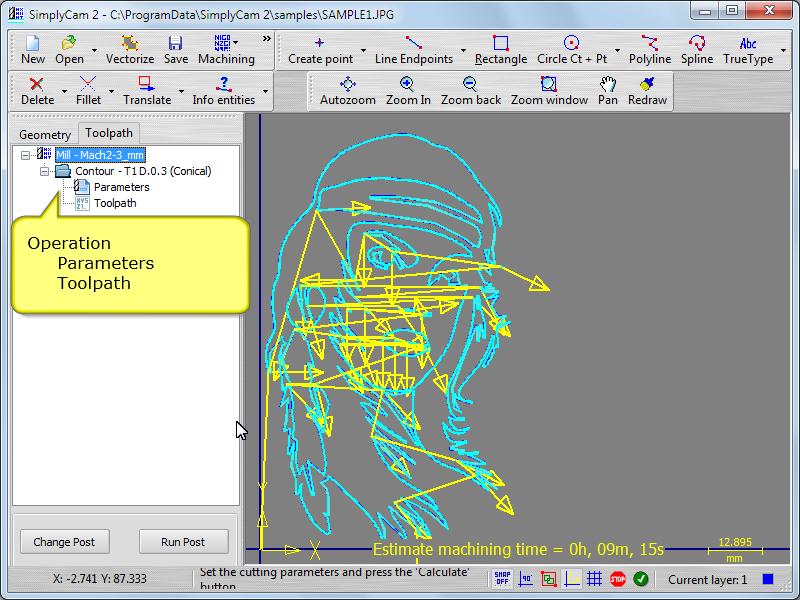
Step 26.
The new operation "Contour" is created in Cnc tree view and the toolpath is diplayed in the graphic area.
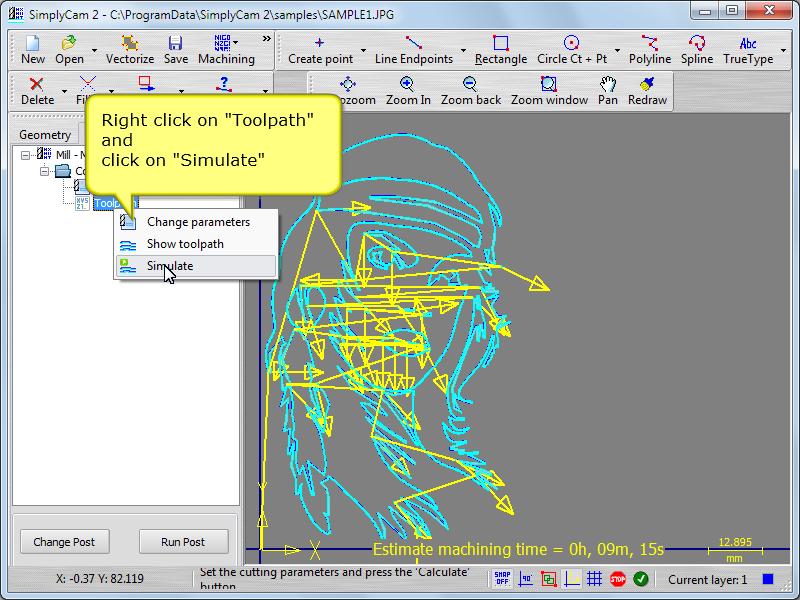
Step 27.
Right click with mouse on the "Toolpath" item and selecl the "Simulate" item from dropdown menu
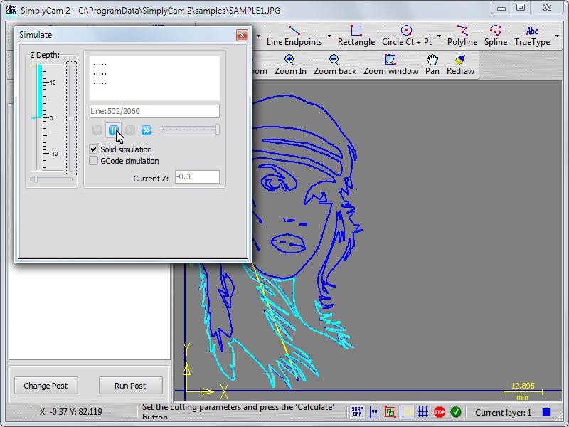
Step 28.
- Press the "Rewind" button.
- Move the slider near to slow position.
- Press the "Play" button to simulate the toolpath (Yellow=Rapid, Cyan=Feed) in the graphic area.
- The "Z Depth" panel indicator, reflect the actual Z tool position (Yellow=Rapid, Cyan=Feed).
Step 29.
Select postprocessor of your Cnc machine.
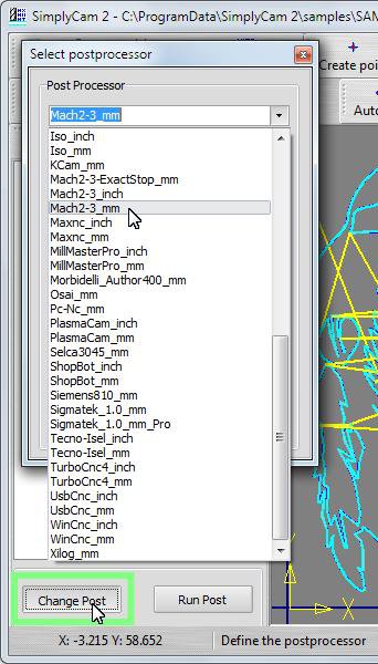
Step 30.
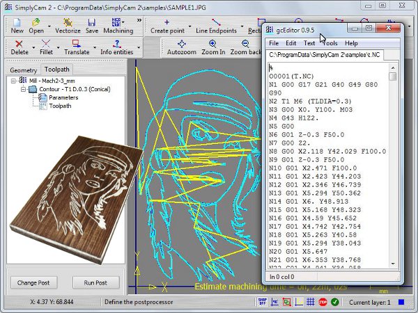
Press "Run Post" button and select the folder and name of Nc file. The editor is displayed with the Nc file processed.
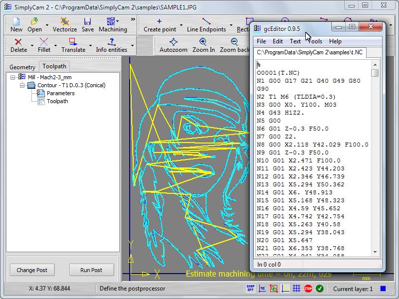
Step 31.
You have successfully created your first Nc file with SimplyCam.
Caution:
CNC machines are potentially dangerous. The post-processor can output code unsuitable for your machine's control. Check the Nc file before sending it to a CNC machine.