
SimplyCam V2. Documentation
Tutorial 3 - Open Dxf file and create the Pocket toolpath
In this tutorial you will open a Dxf file and create the toolpath to remove the material contained in a closed profile.

Caution:
CNC machines are potentially dangerous. The post-processor can output code unsuitable for your machine's control. Check the Nc file before sending it to a CNC machine.
Step 1.
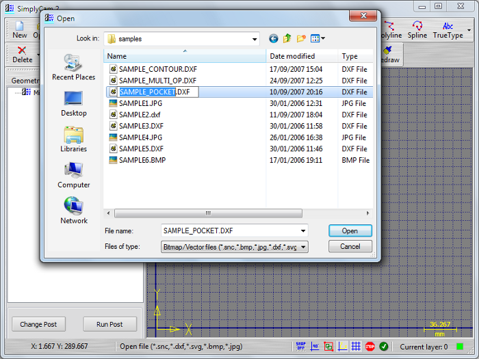
Open the Dxf file with the "Open" button.
Step 2.
Select in "..\SimplyCam 2\Samples\" folder the SAMPLE_POCKET.DXF file.
Step 3.
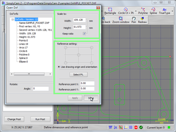
The Info panel will appear with the info and dimension of image.
Scale the drawing dimension if desidered.
Define the reference point of image and press "Apply / Done" button.
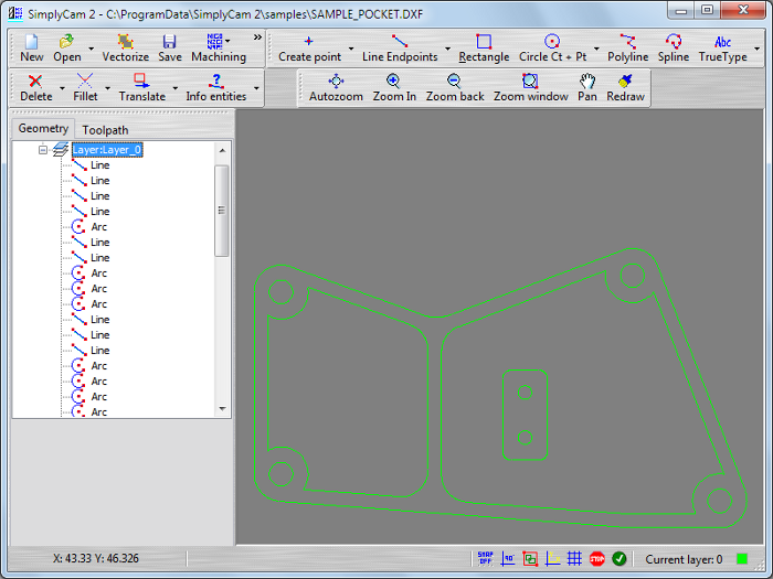
Step 4.
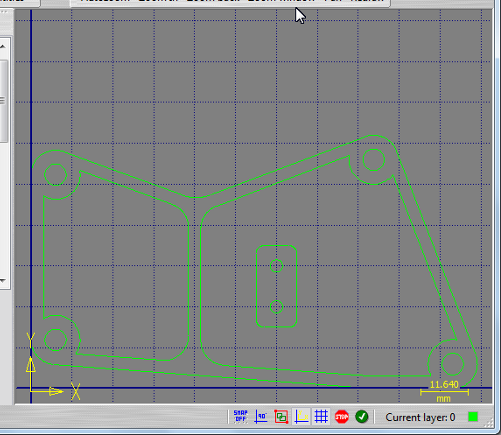
The drawing is displayed in graphic area with grid, axis direction, origin and scale info.
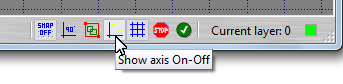
Step 5.
Press the "Show axis" button in status bar on Off state.
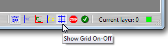
Step 6.
Press the "Show grid" button in status bar on Off state.
Step 7.
The drawing is displayed in graphic area now without grid, the axis direction, origin and scale info.
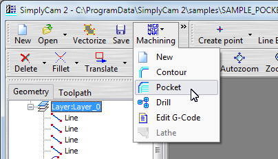
Step 8.
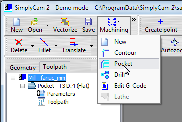
Press "Pocket" in "Machining" menu to go in toolpath section.
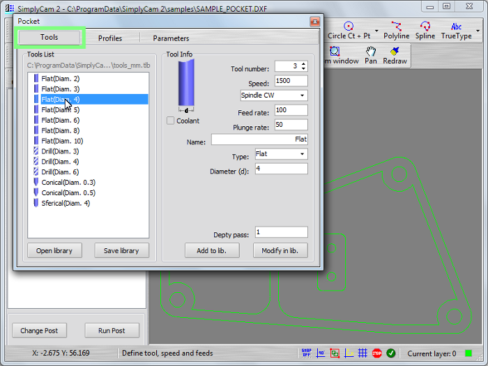
Step 9.
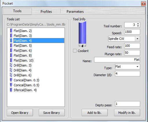
In Tool section click in the Tool List to select the tool. Set feeds and speed of the tool.
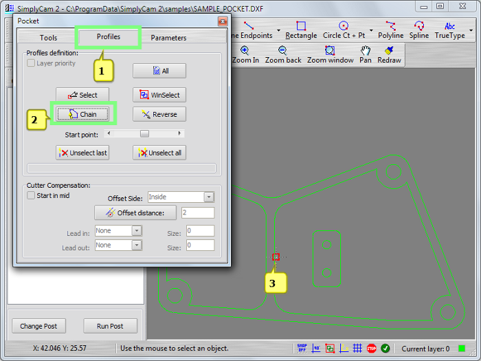
Step 10.
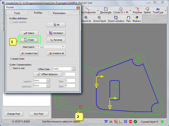
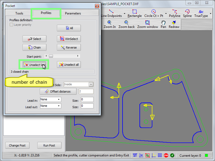
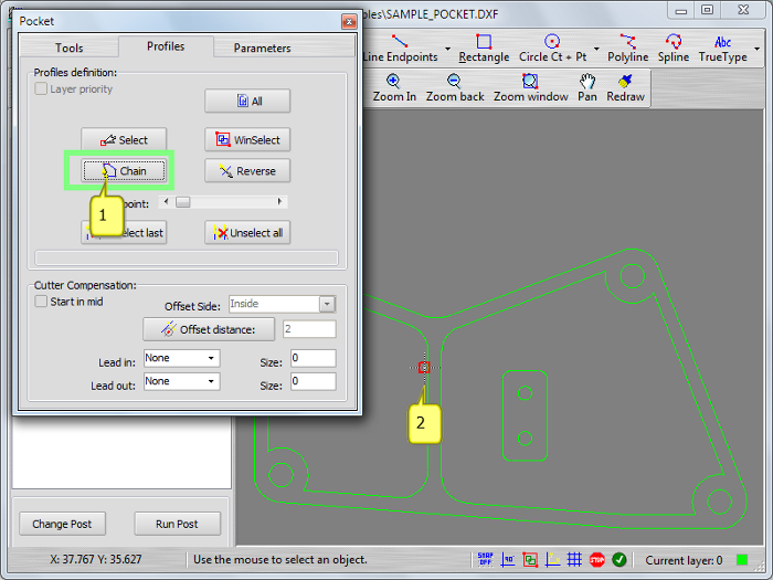
Click on the "Profiles" tab and press the "Chain" button. Pick the geometry near to start point as indicate by red square.
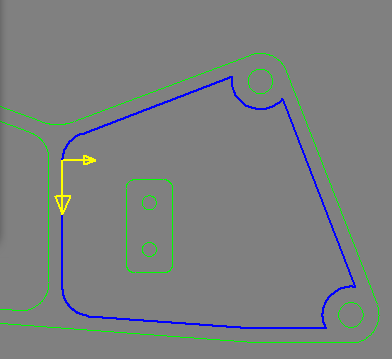
Step 11.
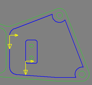
Two yellow arrows appear.
The long arrow indicate the start point of boundary and the direction of toolpath.
The small arrow indicate the side of toolpath.
The blue boundary is the chained profile.
Step 12.
Press the "Chain" button again to define another boundary.
Pick the new geometry such as indicate by red square. This is an island.
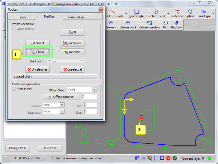
Step 13.
Now the island profile is chained.
Step 14.
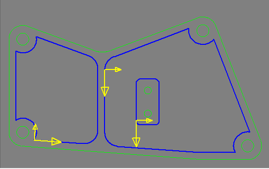
Press the "Chain" button again to define another boundary.
Pick the geometry such as indicate by red square. This is another pocket.
Step 15.
The boundary of another pocket is chained.
Step 16.
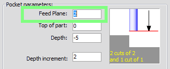
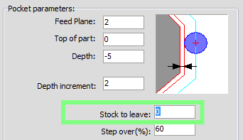
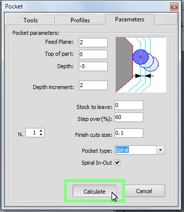
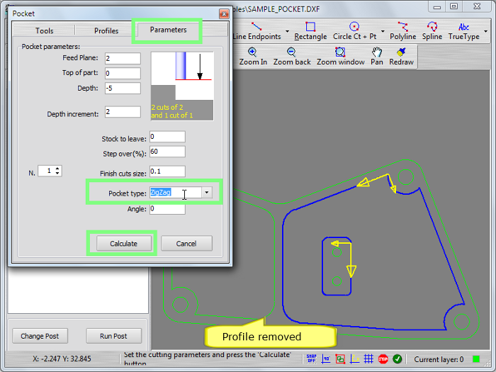
Click on the "Parameters" tab and set up the following parameters:
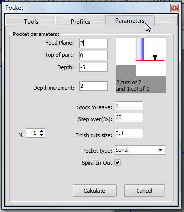
Feed plane: set the height that the tool rapids to (G0) before changing to the feed rate (G1) to enter in the part (absolute).
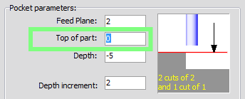
Top of part: set the height of the piece in the Z axis (absolute).
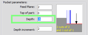
Depth: set the final machining depth (absolute).
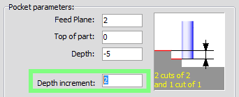
Depth increment: set the maximum amount of material to remove for each Z cut.
Stock to leave: set the amount of material to leave on profile; example if you need a finish pass with other tool.
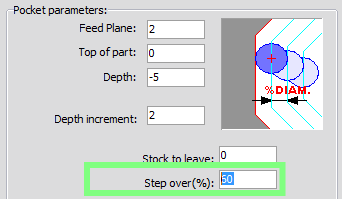
Step over (%): set the spacing between each pass. This is a percentage of the cutter diameter.
Number of finish cuts / Finish cut size: set the number of finish pass and the amount of material to remove for each finish pass.
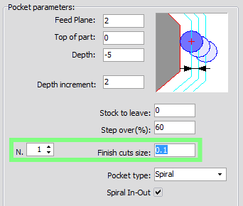
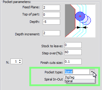
Pocket type: define the cutting methods when roughing the pocket.
Step 17.
Press the "Calculate" button to machining the chained geometry with the cutting parameters.
Step 18.
The new operation "Pocket" is created in the Operation Manager and the toolpath is diplayed in the graphic area.
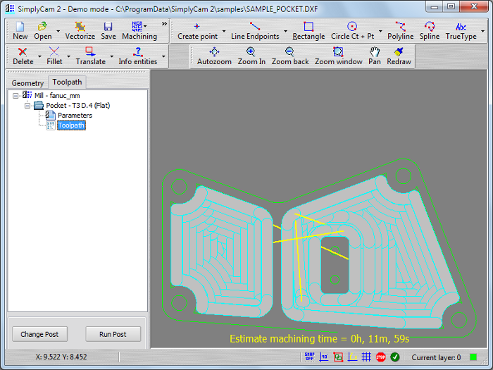
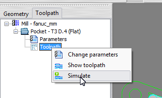
Step 19.
Right click with mouse on the "Toolpath" item and select the "Simulate" from dropdown menu.
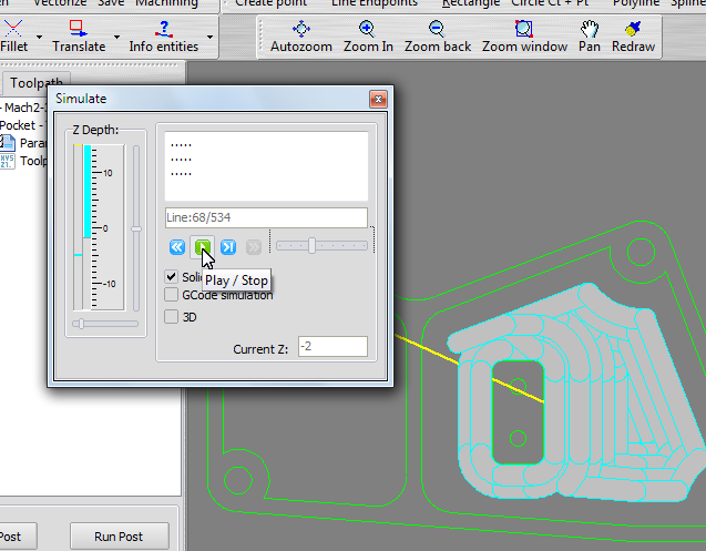
Step 20.
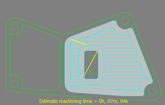
The Simulate dialog is displayed.
- Press the "Rewind" button.
- Move the slider near to slow position.
- Press the "Play" button to simulate the toolpath (Yellow=Rapid, Cyan=Feed) in the graphic area.
- The "Z Depth" panel indicator, reflect the actual Z tool position (Yellow=Rapid, Cyan=Feed).
Step 21.
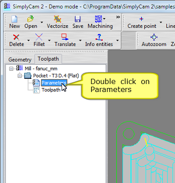
Close the Simulate dialog and edit the parameter of operation.
Double click with mouse on the "Parameters" item or Right click with mouse on the "Parameters" item and select the "Change parameters" from dropdown menu.
Step 22.
In "Proliles" section remove the last profile chained. Press the "Unselect Last" button.
Step 23.
The last profile is removed.
In "Parameters" section change the "Pocket type" parameter in "ZigZag", next press the "Calculate" button.
Step 24.
The new chained geometry is remachined.
Step 25.
Adding new Pocket operation.
Press "Pocket" in "Machining" menu.
Step 26.
No change in the Tool section
Step 27.
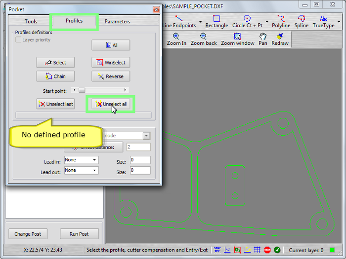
In "Proliles" section remove all profile chained. Press the "Unselect All" button.
Step 28.
Press the "Chain" button. Pick the geometry near to start point as indicate by red square.
Step 29.
Click on the "Parameters" tab and change the "Depth" of pocket and the "Angle" of machining. Press the "Calculate" button.
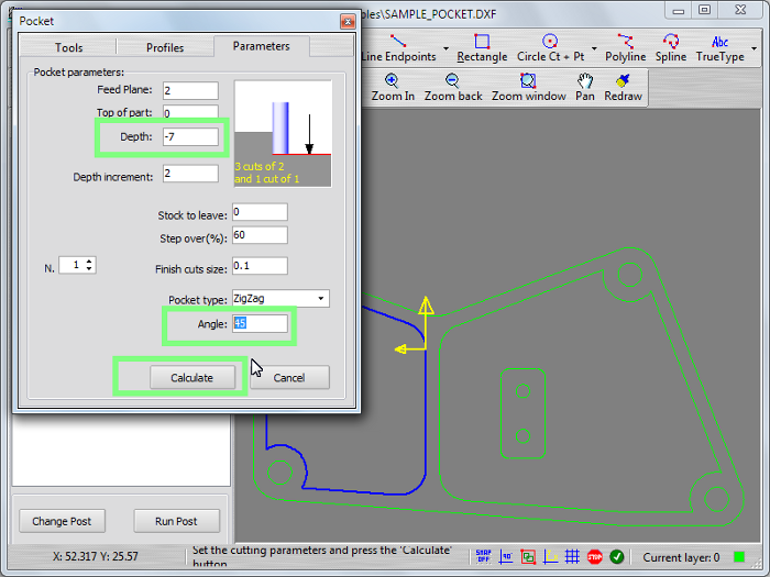
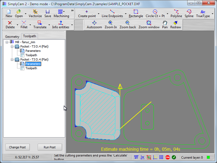
Step 30.
The second operation "Pocket" is created in the Operation Manager and the toolpath is diplayed in the graphic area.
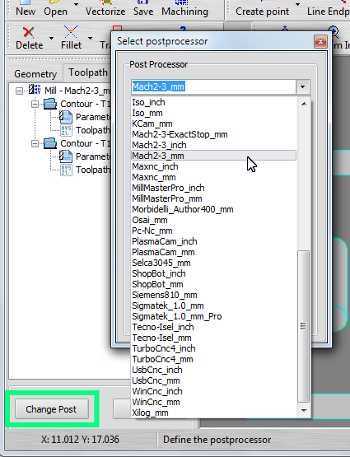
Step 31.
Select postprocessor of your Cnc machine.
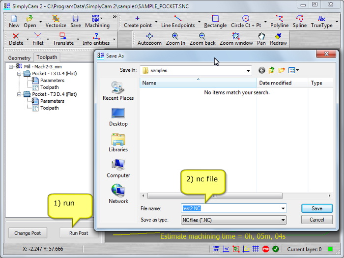
Step 32.
Press "Run Post" button and select the folder and name of Nc file.
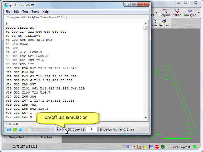
Step 33.
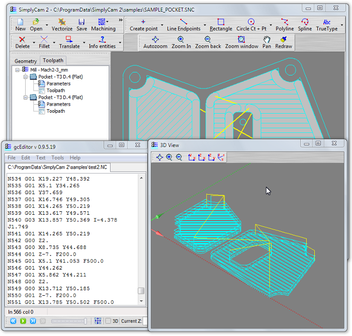
The editor is displayed with the Nc file processed.
Activate (check) the 3D simulation.
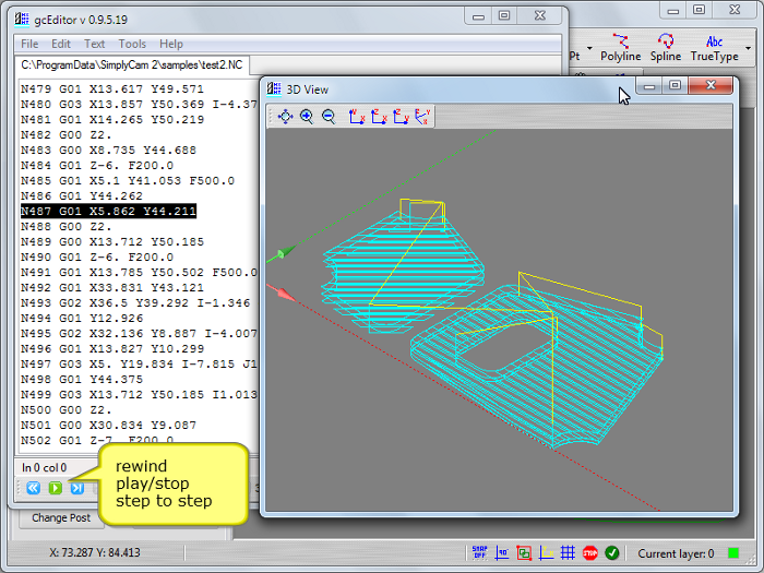
Step 34.
Press the "Rewind" button.
Press the "Play", "Stop", "Step" buttons to simulate the toolpath (Yellow=Rapid, Cyan=Feed) in the 3D graphic area.
You have successfully created the pocket toolpath with SimplyCam.
Caution:
CNC machines are potentially dangerous. The post-processor can output code unsuitable for your machine's control. Check the Nc file before sending it to a CNC machine.